
Understanding Snap-Fit Joints in 3D Printing
Snap-fit joints are a staple in both industrial and hobbyist product design, providing a simple way to assemble parts without screws or adhesives. In 3D printing, mastering snap-fit joints opens up new possibilities for functional assemblies, prototypes, enclosures, and articulated models. However, designing snap-fit features for additive manufacturing requires a tailored approach, taking into account the unique strengths and limitations of 3D printing processes.
Types of Snap-Fit Joints
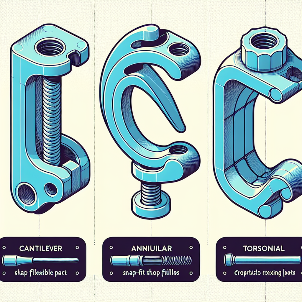
There are several common types of snap-fit joints used in 3D printed assemblies:
- Cantilever Snap-Fit: Features a flexible arm that locks into a mating component. It’s the most widely used and easiest to design for FDM printing.
- Annular Snap-Fit: Common for cylindrical parts (like lids and containers), these use a circular ridge that deforms temporarily to snap into place.
- Torsional Snap-Fit: Relies on twisting motion and is less common in 3D printing due to complex stress distribution.
Understanding the right type for your application is the first step to reliable assemblies.
Material Selection Matters
Selecting the proper filament is crucial. Materials with good flexibility and fatigue resistance work best for snap-fits. Here’s a quick comparison:
- PLA: Easy to print but brittle; best for prototypes or low-stress snaps.
- PETG: More flexible and impact-resistant, making it a good choice for functional snap-fits.
- ABS: Offers excellent flexibility and toughness but may require an enclosed printer to prevent warping.
- TPU: Highly flexible, great for living hinges and very robust snaps but can be tricky to print with precision.
Always consider the end-use environment: exposure to UV, chemicals, or temperature swings will also affect your choice.
Best Practices for Designing Snap-Fit Joints
1. Parameterizing the Cantilever Arm
The thickness, length, and width of the cantilever arm directly affect flexibility and strength. As a rule of thumb:
- Longer arms are more flexible, while shorter arms are stiffer.
- Thinner cross-sections allow for more deflection but may break under excessive load.
- For most FDM prints, an arm thickness of 1.5 – 3 mm and length 10 – 20 mm is a good starting point.
Use fillets (rounded transitions) at the base of the arm to reduce stress concentrations and prevent crack initiation.
2. Designing the Retention Feature
The snap feature (hook or bead) must be large enough for secure retention but not so big that it’s impossible to assemble. The undercut should allow for enough deflection of the arm without exceeding the elastic limit of the material.
A typical engagement angle is 30–45°, with a lead-in chamfer of 15–20° to facilitate assembly.
3. Allowing for Tolerances and Clearance
FDM printers have inherent accuracy limitations and part shrinkage, so always provide adequate clearance:
- For most FDM prints, a clearance of 0.2–0.5 mm between mating parts is safe.
- SLA and other resin prints can go tighter, down to about 0.1 mm, but test fits are always recommended.
Account for the layer direction: cantilever arms printed along their length (lying flat) are stronger than those printed on edge, which are prone to snapping at layer lines.
4. Iterative Prototyping
The best designs result from rapid prototyping and real-world testing. Start with simple geometry and incrementally adjust:
- Test different arm thicknesses and lengths.
- Try various retention feature sizes and shapes.
- Assemble, disassemble, and observe wear or failure points.
Assembly and Post-Processing Tips
– Ensure the prints are free of stringing and blobs; clean up with a hobby knife or fine sandpaper if necessary.
– If the snap-fit is too tight, gently file the mating surfaces for a smoother action.
– For repeated use, consider applying a touch of silicone grease to reduce wear.
Common Issues and How to Fix Them
- Snaps break on first use: Arm too short/thick, or printed in the wrong orientation. Increase arm length, reduce thickness, or rotate the part for optimal strength.
- Snaps are too loose: Tolerance is too high or arms are too flexible. Increase engagement depth or decrease clearance slightly.
- Assembly is impossible: Undercut too deep, material too stiff, or insufficient chamfer. Redesign the feature for easier entry.
Conclusion
Designing snap-fit joints for 3D printed assemblies is both an art and a science, blending considerations of geometry, material properties, and printer capabilities. With thoughtful design, careful material selection, and a willingness to prototype, you can achieve assemblies that are reliable, user-friendly, and fully optimized for additive manufacturing. Start experimenting with snap-fits in your next project, and you’ll quickly unlock new possibilities in your 3D printing workflow.
Leave a Reply