
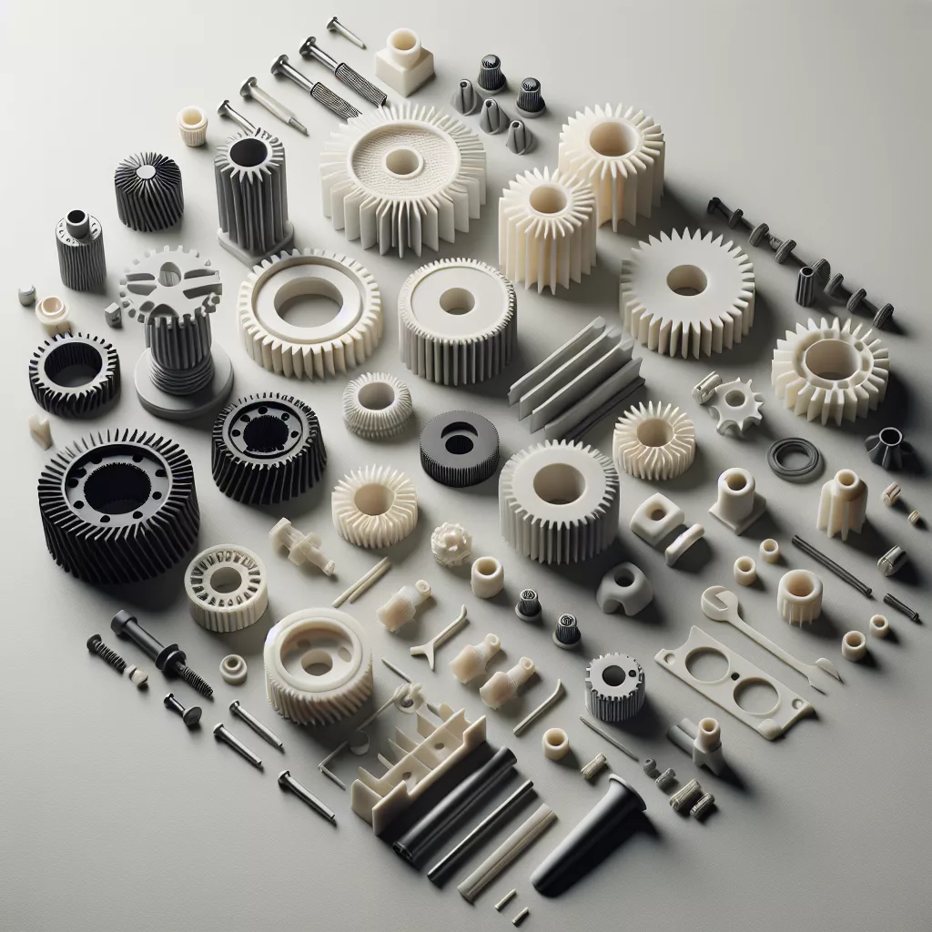
Understanding Functional Gears and Mechanical Parts
3D printing has revolutionized the way hobbyists, engineers, and designers approach the prototyping and manufacturing of gears and mechanical parts. Unlike cosmetic models, functional gears are expected to transmit force, endure wear, and operate smoothly within assemblies. Successfully printing these parts means understanding both the design and the limitations of your 3D printer.
Choosing the Right Material
The choice of material is critical for functional parts. For gears and mechanical components, here are the most common options:
- PLA: Easy to print and dimensionally stable, but brittle and wears quickly under stress.
- PETG: Offers more flexibility and durability than PLA. Decent for light-duty gears.
- ABS: Stronger and more heat-resistant than PLA and PETG, but can be prone to warping.
- Nylon: The top choice for high-strength, low-friction gears. Flexible, tough, and handles wear extremely well. Requires proper print environment (enclosed printer recommended).
- Polycarbonate & Composite Filaments (Carbon Fiber, Glass Fiber): Exceptional strength and wear resistance for mission-critical applications.
For most home and desktop users, Nylon is the best balance between printability and performance. Use a hardened nozzle for fiber-filled filaments, as they can be abrasive.
Design Tips for Reliable Mechanical Parts
When designing gears and mechanical components for 3D printing, several best practices ensure optimal function:
- Use Appropriate Tolerances: FDM printers have limitations. For interlocking or moving parts, leave at least 0.2–0.3mm clearance between surfaces.
- Optimize Tooth Profile: For gears, use involute tooth profiles rather than simple triangles or rectangles. Popular CAD tools and plugins can generate these accurately.
- Avoid Thin Walls: Make sure gear teeth and load-bearing sections are at least 2–3 nozzle widths thick to minimize risk of breakage or poor layer adhesion.
- Filleting and Chamfering: Add fillets or chamfers to reduce stress concentrations and improve printability, especially at the base of gear teeth.
- Orientation Matters: Print gears flat on the build plate with teeth facing upward for best accuracy and strength. Avoid vertical orientation for gears, as layer lines can cause weakness at the tooth root.
Print Settings for Strength and Precision
Dialing in your slicer settings can make the difference between a squeaky, wobbly gear and a smooth, durable mechanical part.
- Layer Height: Choose a small layer height (0.1–0.15mm) for smooth surfaces and precise meshing. For larger, heavy-duty gears, 0.2mm may suffice.
- Infill: Use at least 50% infill for gears; 100% infill is ideal for maximum strength.
- Perimeters: 3–4 perimeters (walls) help reinforce teeth and reduce the risk of splitting.
- Print Speed: Slow down for precision. 30–40mm/s is a good starting point for gears.
- Cooling: Minimal cooling for Nylon and ABS. PLA and PETG can use standard cooling.
- Adhesion: Use rafts, brims, or adhesion aids, especially for warp-prone materials like ABS and Nylon.
Post-Processing for Performance
After printing, some post-processing steps can greatly improve the function and longevity of your gears and parts:
- Deburring: Use a sharp hobby knife or sandpaper to remove stringing, blobs, or sharp edges.
- Lubrication: Apply a small amount of PTFE (Teflon) or silicone grease to reduce friction and wear.
- Annealing: Heat-treating (annealing) Nylon or Polycarbonate can increase strength and reduce internal stresses—but ensure to follow manufacturer guidelines to avoid warping.
- Test Fit: Assemble and run your gears or mechanical assembly by hand to check for binding or excessive slop. Adjust your CAD design and reprint if necessary.
Common Pitfalls and How to Avoid Them
Based on years of experience, here are the most common issues to avoid:
- Skipping Supports: Overhangs, especially gear teeth, may need support. However, minimize supports to reduce cleanup.
- Ignoring Shrinkage: Materials like Nylon shrink as they cool. Print test pieces and adjust your design for a perfect fit.
- Underestimating Loads: 3D printed gears aren’t as strong as injection-molded or metal gears. Always consider the mechanical limits of plastic, and design accordingly.
- Improper Orientation: Always print gears lying flat to maximize strength along the most stressed axis.
Conclusion
Printing functional gears and mechanical parts is a rewarding application of 3D printing technology. By selecting the right material, using optimized print settings, and designing with the printer’s capabilities in mind, you can produce smooth-running, durable components for your next project—whether that’s a robot, a clock, or a custom mechanical assembly. Remember to test, tweak, and iterate: every print is a step closer to perfection.

Leave a Reply